RF-DAQ Wireless Remote IO
RF-DAQ units add wireless remote IO capability with each RF-DAQ unit having a range of industrial IO allowing for easy data acquisition of remote analog and digital signals from one or more DAQ IO outstations via 868/900Mhz and high power 900Mhz ultra-long range wireless links. This is done using the industry proven XBEE DigiMesh RF technology.
Digi XBEE 900MHz Datasheet
Digi XBEE 868MHz Datasheet
The RF-DAQ units have industrially hardened IO providing both analogue and digital inputs along with relay driving outputs. This allows direct control of remote equipment from a central point. RF-DAQ units can operate on wide power DC input voltage range of 6-28V and are rated for -40 to +60°C ambient temperature .
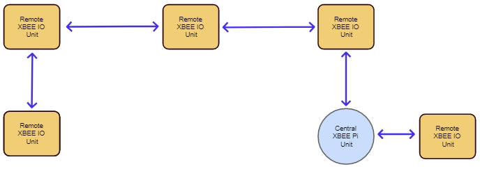
Operating in DigiMesh RF topology mode means the central Pi unit does not have to be in RF range of all outstations as outstations can relay messages to the target transparently, considerably increasing the range of deployment.
Using this topology the XBEE network can be easily configured using basic bash and python scripts allowing the central device to poll each of the outstations and for new readings periodically.
Unit Specification
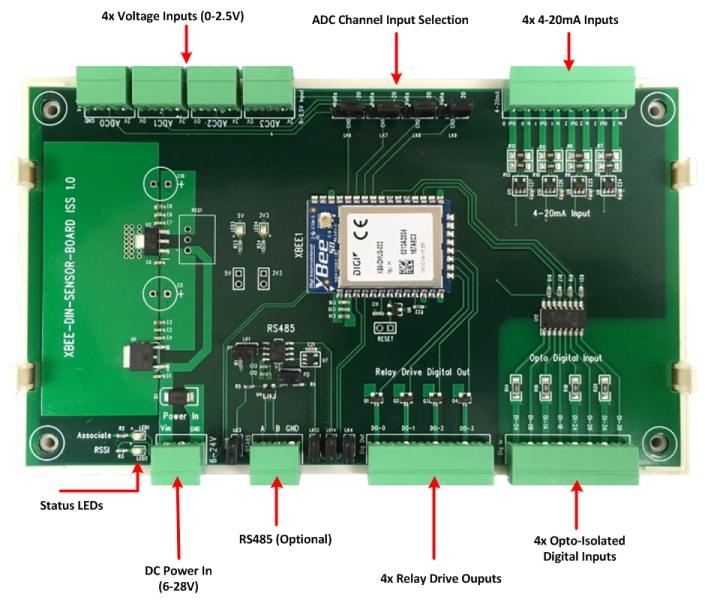
The RF-DAQ board has the following IO capability :
- - Wide 6-28V DC input operating range
- - 4 x Opto Isolated Digital Inputs (5-30V)
- - 4 x ADC Channels individually selectable as either 0-2.5V or 4-20mA Analogue Inputs
- - 4 x Open collector Digital out/relay drivers for upto 24V
- - Units operate in DigiMesh networking topology allowing for greater deployed network range
- - Optional RS485 Interface (serial comms mode is mutually exclusive with IO mode)
- - Optional IP65 cased version with RS485 & RS232 interfaces
The Voltage ADC inputs are compatible with Analogue Devices TMP36 wide range temperature sensors, care should be taken with cabling for these devices to both reduce signal noise and volts-drop.
The XBEE module's ADC inputs are 10bit precision, which translates to the following tolerances on readings taken (sensor accuracy not included) :
| Voltage | ±0.004V |
| 4-20mA | ±0.04mA |
| Temperature | ±0.5°C |
Plug Pin Outs
DC Power In
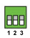
1 Positive Input (6-28V)
2 Not Connected
3 0V
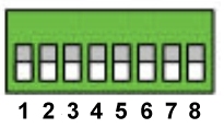
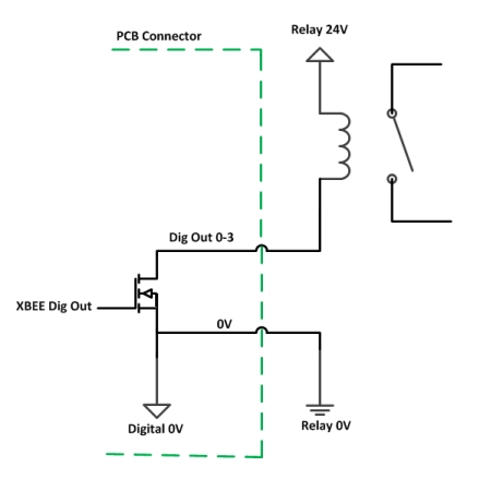
Relay Drive Digital Out
Outputs are open-collector style with internal protection diodes, so providing the path to 0V rather than a sourcing positive voltage, these will drive an inductive load (relay) with a coil voltage of up to 24V
1 Digital Out 0
2 0V
3 Digital Out 1
4 0V
5 Digital Out 2
6 0V
7 Digital Out 3
8 0V
Opto Isolated Digital Inputs
This gives 4 independently driven Bi-directional (AC) opto-isolated inputs, with a wide 5-30V input range, as such the input can be wired either way around with the positive voltage side on either A or B terminal.
1 Digital In 0 A
2 Digital In 0 B
3 Digital In 1 A
4 Digital In 1 B
5 Digital In 2 A
6 Digital In 2 B
7 Digital In 3 A
8 Digital In 3 B
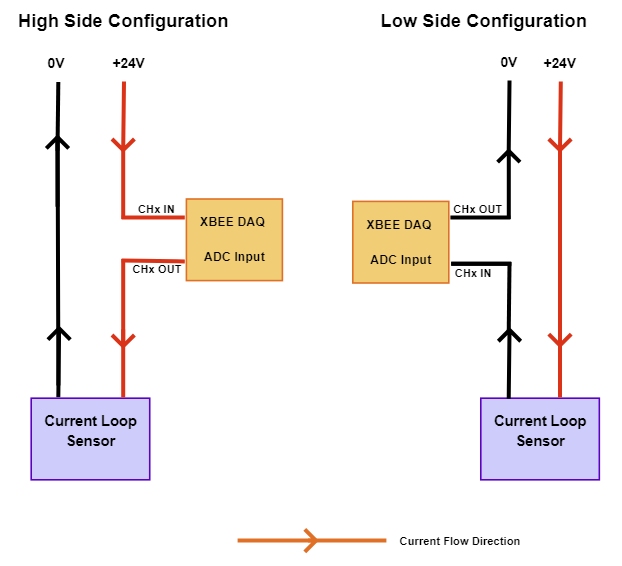
Analogue Inputs - 4-20mA Current Loop
This input gives 4x current loop inputs compatible with High Side or Low Side operation.
The voltage read at the XBEE ADC input is directly proportional to the current flowing e.g. 0.4V input = 4mA and 2.0V = 20mA
1 CH3 IN
2 CH3 OUT
3 CH2 IN
4 CH2 OUT
5 CH1 IN
6 CH1 OUT
7 CH0 IN
8 CH0 OUT
Analogue Inputs - Voltage
Pin outs are the same for all 4 channels
1 = +3.3V DC Sensor Supply
2 = Sensor Input (0-2.5V DC)
3 = Sensor 0V
RS485 -- Optional
1 = RS485 A
2 = RS485 B
3 = RS485 Ground
Link Settings
Analogue Input Channel Selection
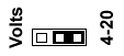
This link allows you to select which type of input is fed into the respective ADC channel, either the 4-20mA level or the voltage input and operates on a channel by channel basis.
LEDs
RSSI
Blinks when data received, brightness is proportional to signal strength
Associate
Blinks when XBEE module is running
Setup Instructions
XBEE RF modules have the following key properties
- User definable alphanumeric “Node Name”
- Unique factory set 16 Byte hex ID (aka Source Address)
- User definable 16 Byte hex destination/target comms address
- User defineable Network ID
- API IO or Transparent Comms operating mode
- Optional AES encryption of wireless data transmission giving an extra layer of security
- Zigbee/DigiMesh Networking topology allowing for greater deployment range
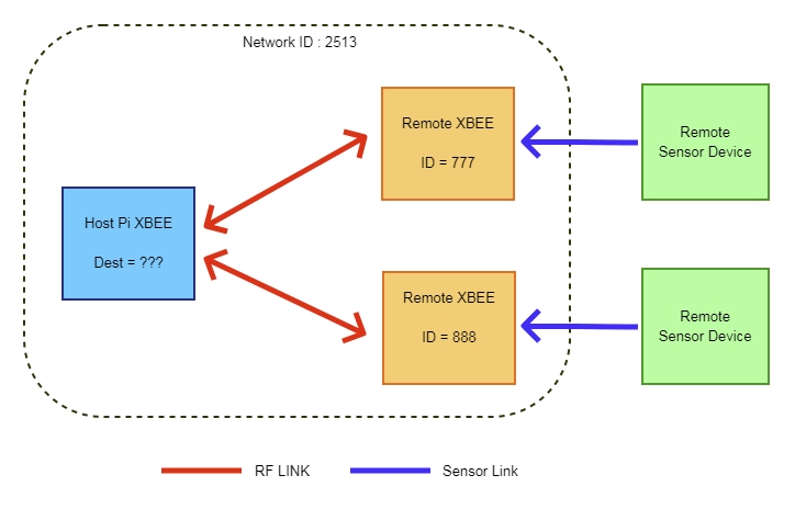
For XBEE devices to communicate with each other in API IO mode they need only to be on the same network ID as unlike transparent comms mode all transmitted packets between nodes contain the necessary source/destination routing information. For all RF-COM/RF-DAQ units we pre-configure all units to use network id '2513'
The diagram below this shows the central Pi unit fitted with an XBEE RF Card, allowing the Pi unit to poll one or more remote RF-DAQ units by directly addressing a destination unit's XBEE module ID to obtain sensor readings back.
The address ID of the XBEE module, as factory set by Digi, is read-only and is marked on the top of the module.
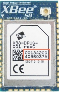
To make identification process easier we pre-configure the XBEE module in each DAQ unit with a unique alphanumeric Node Name identifier (20 characters max) in the format XBEEIOxxxxxxx and is printed on the top of the enclosure. We have created setup and configuration scripts that allow you to reference the units by this name for ease of use rather than the XBEE module ID.
The RF-DAQ units can be fitted with different versions of the XBEE/XBEE PRO modules, however our software scripts only support the DigiMesh module types.
Software Support
We have provided a series of python scripts supporting the DigiMesh modules to allow quick and easy configuration of the system to allow fast application integration, to install these utilities follow the instructions on the GitHub page here to install the python scripts
XBEE-RF-DAQ Github Project Page
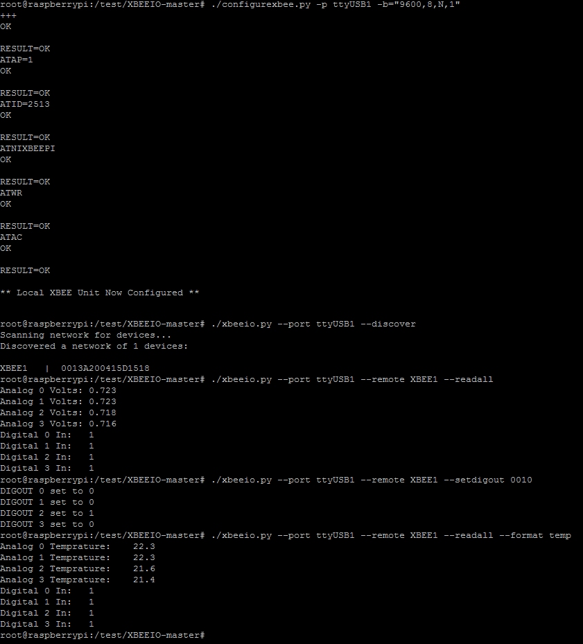
With the Python scripts and libraries installed you can interact witht the RF-DAQ unit easilly using the command line tools as shown below
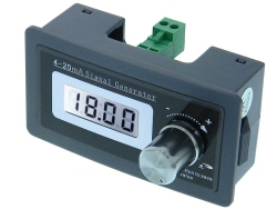
4-20mA Signal Generator
To simulate 4-20mA sensor readings you can use a low cost current loop simulator such as the type below, these typically have 5% tolerance but are adequate for a test/development environment :
Wire this up in high side configuration using a 12V or 24V power supply
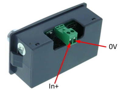
You should now find that as you vary the current on the simulator using the dial the readings will change accordingly.