MyPi Integrator Board Pinout
Connector Pin Outs
J20 CAM0
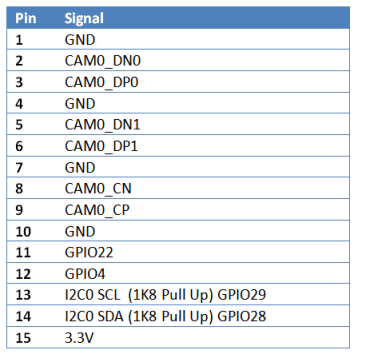
J21 CAM1 – Default Camera
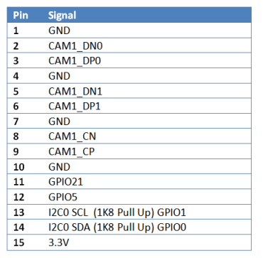
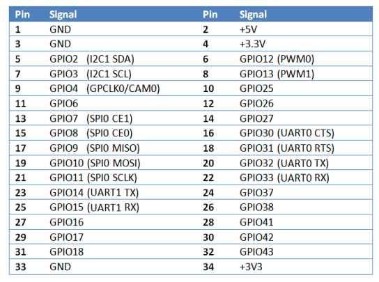
J10 34Way Female ASIO Connector
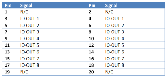
J11 20Way Female ASIO Output Connector
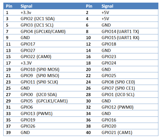
J8 40Way Male Raspberry Pi 2 HAT I/O Connector
J15 RS232 Connector (wired for Cisco Console Cable)
Long cable RS232 Cable lengths possible using CAT5e Cable
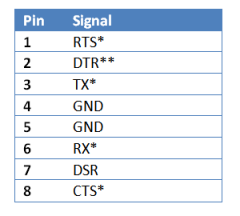
*Only these signals are available
** Pulled to +5V via Link LK9
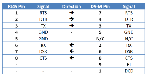
Use RJ45/D9M adapter for standard D9M pinout as below:
Alternatively use compatible Cisco 72-3383-01 RJ45 - DB9F (Cross-Over) Console Cable:
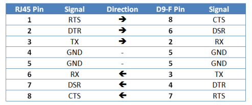
Direction shown is from the PCB Connector
J9 8Way IO 2-Part Screw Terminal Connector
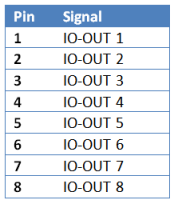
J25 allows usage by external devices, e.g. RPi HAT boards
J1 3Way Power In 2-Part Screw Terminal Connector
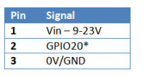
*Enable by shorting SMT Link LK11 on reverse
J24 Internal Power Feed

J23 Audio Out

Audio uses PWM0_OUT/GPIO40 & PWM1_OUT/GPIO45
J13 LAN Connector
Standard
J14 Dual USB 2.0
Standard
J19 HDMI OUT
Standard, including CEC and I2C inputs
J12 Micro USB-B CM Flash Programming Port
Standard – Set J6 to 1-2 to use
J17 Hinged Micro SD Card Holder
Standard
J16 Hinged SIM Holder
Standard
J15 Mini PCI-E
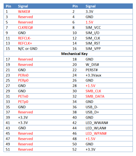
Signals in RED are not connected/available
J5 SO-DIMM Connector For Raspberry Pi Compute Module
Compatible with Raspberry Pi Compute Module only.
LEDS
LED1 -GREEN
GPIO36 – Low Level Activates LED
LED1 -RED
GPIO35 – Low Level Activates LED
LED2 –GREEN/-RED
Driven directly by on board USB UART to show RX/TX indication