MyPi Integrator Board Serial Port Configuration
There are three on board serial ports available on the MyPi base board, UART0&1 are direct from the RPi module and the third is via the on board FTDI 230X USB-UART device.
|
Name |
Port |
Primary Usage | RTS/CTS? |
| UART0 | /dev/ttyAMA0 | PL011 UART | Yes** |
| UART1 | /dev/ttyS0 | Mini UART - Linux Serial Console | No |
| USB-UART | /dev/ttyS1* | Full 16550 Compliant UART | Yes |
* Will appear as a ttyUSBx port, udev rule will create /dev/ttyS1 symlink short-cut
** RTS/CTS lines optional and configured via device-tree overlays (not suitable for 485 flow control)
Note that UART1 was originally intended as a serial console rather than a full featured UART and so has a few quirks in the settings it can reliably use (as well as the baud rates being affected by the clock rate of the CPU). For this reason care should be taken to assess it's suitability for usage, for more information see this web page : HERE
UART0 is the preferred choice when using for serial communications between devices due to having a more complete feature set.
USB-UART is permanently enabled as RS232 via the RJ45 socket on the front face (wired to Cisco console cable format) to give maximum cable distance.
The GPIO pins UART0 & 1 appear on are user-definable via device tree overlays
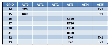
Device-tree overlays for UART0 and 1 are available allowing configuration of which pins these serial lines are to appear on, these can all be configured via the device-tree dt-blob.bin or the overlay section in config.txt
It should be noted that on older kernels (pre-4.9.x) both Raspberry Pi serial ports have a minor quirk where on opening the serial port a single spurious character is sent, this currently has no work-around but all activity after this initial pulse work fine.
Device-Tree Overlay Documentation
GPIO Pins and Alternate Functions