RF-COM Wireless Remote Serial Controller
RF-COM units allow wireless, transparent, serial communications between a local RF card (fitted to the Pi unit) and one or more remote outstations via 868/900Mhz and high power 900Mhz ultra-long range wireless links. This is done using the industry proven XBEE DigiMesh RF technology.
The remote RF-COM units have a single serial port which is selectable as either a D9 RS232 interface or a half duplex RS485 Interface (with auto direction control) giving total flexibility in the setup. The remote devices can operate on a wide power DC input voltage range of 6-28V and are rated for -40 to +60°C ambient temperature making it ideal for use in an industrial environment.
Digi XBEE 900MHz Datasheet
Digi XBEE 868MHz Datasheet
The wireless technology employed is best imagined to operate as if having one or more (very long) serial cables running between the central Pi unit and each of the remote outstations with the ability to swap which one is have connected at any one time under software control. The host serial port side is also agnostic regarding whether the end point is connected to the remote device using RS232 or RS485 link.
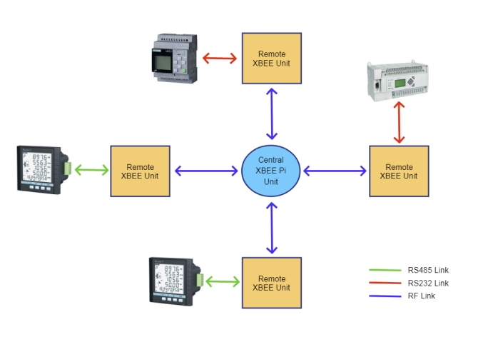
All data sent to the serial port of the local XBEE RF module installed in the Pi unit is wirelessly re-transmitted directly to the target remote XBEE, the remote XBEE's then sends this received data out it's serial port unaltered and onto the remote device, any serial response the remote XBEE receives (from the attached device) is then re-transmitted back to the originating host unit, so the same process but in reverse.
XBEE RF modules operate in DigiMESH topology mode, this means the XBEE module inside the Pi unit does not have to be in RF range of all target outstations as the outstations will self-organise to relay messages to the target transparently (provided the remote units are all within range of at least one other other).
Using this topology the network can be easily configured using basic bash and python scripts allowing the Pi unit to poll each of the devices in turn to collect data from each remote outstation
Setup Instructions
XBEE units have the following key properties
- - User definable alphanumeric node name
- - Unique factory set read-only 16 Byte module ID (aka 'Source Address')
- - User definable destination module address
- - Operating mode (either 'API IO' or 'Transparent Comms' modes)
- - Network ID (all XBEE units need to have the same network ID)
- - Optional AES encryption of wireless data transmission
- - MESH Networking topology allowing for greater deployment range
For XBEE devices to communicate they need to be on the same network ID and have reciprocating target data transmission address IDs. For all RF-COM/RF-DAQ units we pre-configure all units to use network id '2513'.
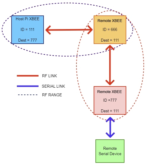
In the diagram below we show a simple 1:1 relationship, here any data sent to the Host XBEE’s serial port will be re-transmitted unaltered by the remote XBEE unit to the remote serial device, any data received by the remote XBEE unit will in-turn be re-transmitted back to the host XBEE unit.
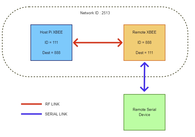
Note that from the host unit’s perspective it doesn’t matter if the remote serial device is connected to the remote XBEE COM unit using an RS232 or RS485 connection.
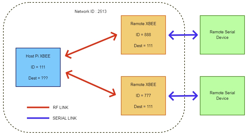
In a more advanced 1:Many relationship this configuration alters a little with each of the remote units configured to have their target desination address set to the same host unit, but the host unit can be configured to talk to a diffent remote unit by simply changing the target destination address setting on the host XBEE unit before a serial transaction. This gives you effectively the ability to virtually “plug in” serial cables going to different end devices.
The mesh networking topology allows communication with remote nodes even if they are not within range of the host unit. In the example below the host unit is able to communicate with remote node 777 as node 666 is within range of both and can relay the messages between nodes and so acts as a relay. This message relay process is transparent once the initial networking discovery setup process has been completed.
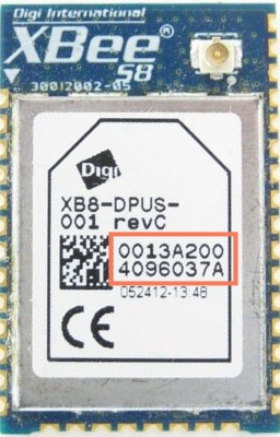
The ID of the XBEE unit is factory set by Digi, read-only and marked on the top of the module
To make identification process easier we pre-configure each unit’s Node Name with a unique alphanumeric identifier (20 characters max) and usually in the format XBEECOMxxxxxxx which is printed on the top of the enclosure. We have created setup and configuration scripts that allow you to reference the units by this name rather than the XBEE module ID.
The XBEE COM module can fit different versions of the XBEE/XBEE PRO modules, both the Surface Mount and Through Hole models, however our software scripts only suppport the DigiMesh module types. Only one module may be fitted at a time.
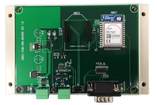
Plug Pin Outs
DC Power In
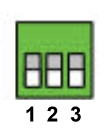
1 = Positive Input (6-28V)
2 = Not Connected
3 = 0V
RS485

1 = RS485 A
2 = RS485 B
3 = RS485 Ground
Link Settings
RS232 Mode
![]()
RS485 Mode
![]()
RS485 Bus Termination
Fit Link to enable 120R RS485 Bus Terminator (Default)
LEDs
RSSI
Blinks when data received, brightness is proportional to signal strength
Associate
Blinks when XBEE module is running
Software Support
We have provided a series of python scripts supporting the DigiMesh modules to allow quick and easy configuration of the system to allow fast application integration, to install these utilities follow the instructions on the GitHub page here to install the python scripts
XBEE-DIN-COM Github Project Page
Demo
Assuming the Pi platform is running the demo OS with mbpoll installed and configured, if not install mbpoll from the website below
Linux Modbus Polling Program Github Page
For an example demo setup you will need the following :
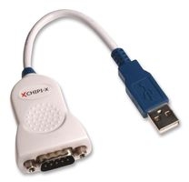
1 or more USB to RS232 adapters like this :
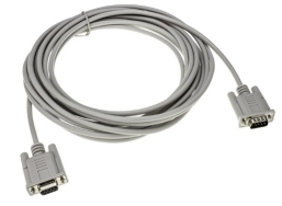
A D9-Female : D9-Female Null Modem Cable Like this :
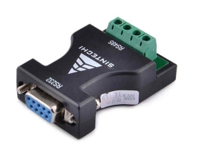
Optionally a RS232 to RS485 Converter Like this
Finally Install Windows Modbus Slave Simulator :
Windows Modbus Slave Simulator
Connect up the devices as below and configure the XBEE COM unit’s serial mode links appropriate to the interface type in use

Configure the Modbus Slave Simulator so 2 each running instance is “connected” to a different virtual COM port (created by the USB to RS232 adapter) and sample values are entered. In our case one simulator is connected to COM4 and the other to COM19 (9600 8N1 are the default XBEE baud rate settings)
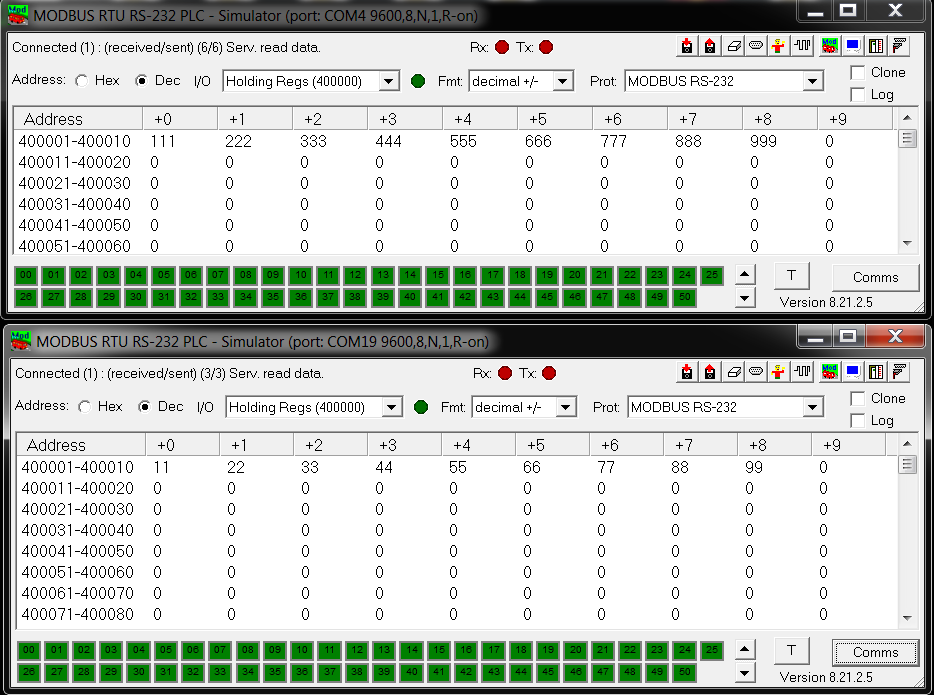
Next log into the Pi unit and run the setup sequence as shown below.
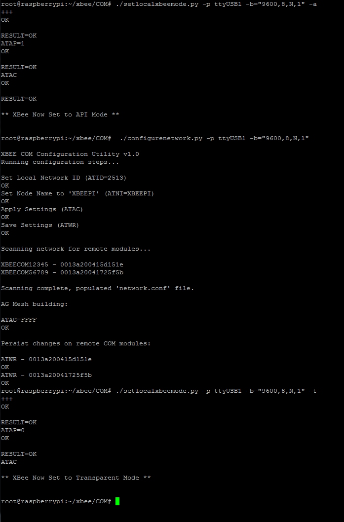
Note that the first setup part only needs to be done once (or when adding more remote COM units), this will configure the Pi Host XBEE module for use and scan the XBEE network for remote COM units (storing these details in network.conf file for later use)
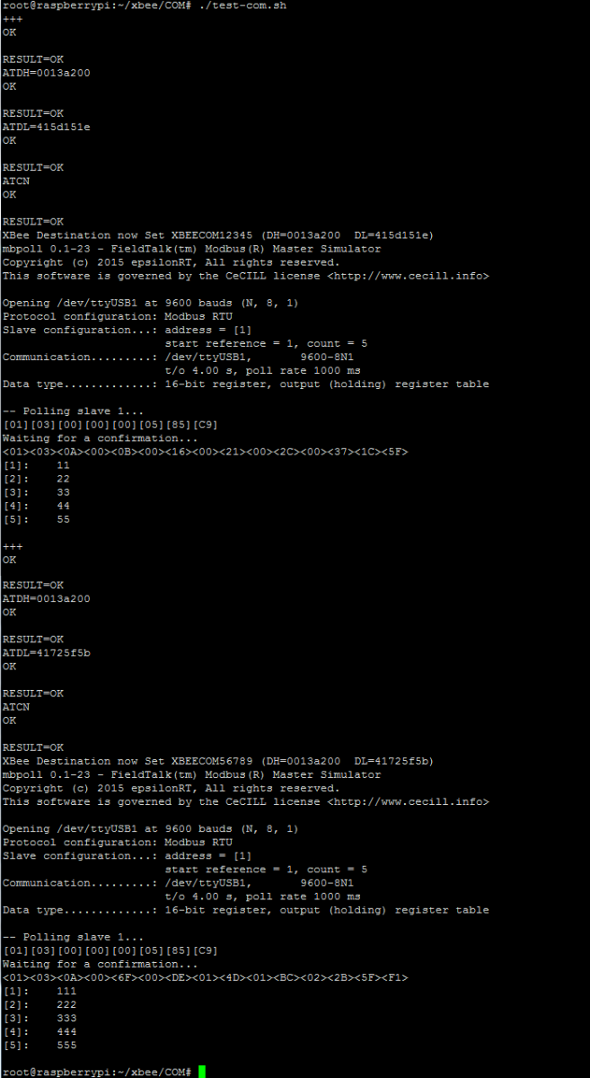
With that done we can then use setlocalxbeedest.py to select which remote XBEE COM unit we are targeting for a Modbus request. To see an example setup for gathering data from 2 units see the bash script file test-com.sh
