Flashing The Raspberry Pi Compute Module
Programming Sequence
Whilst development kits come with the Demo OS pre-installed, this section describes how to write a new disk image to the Compute Module. This section mainly follows the procedure from the Raspberry Pi website guide here :
Raspberry Pi Compute Module Documentation
First of all download the windows USB boot installer, this will install a program we'll use later called RPi-Boot :
Windows Raspberry Pi Compute Module Boot Loader
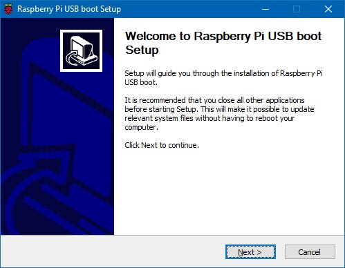
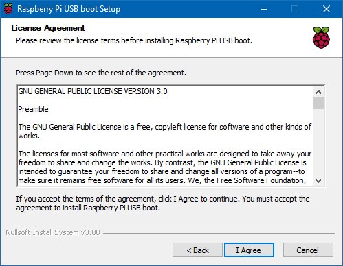
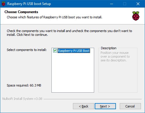
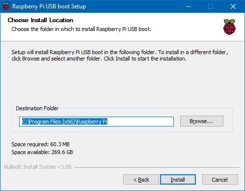
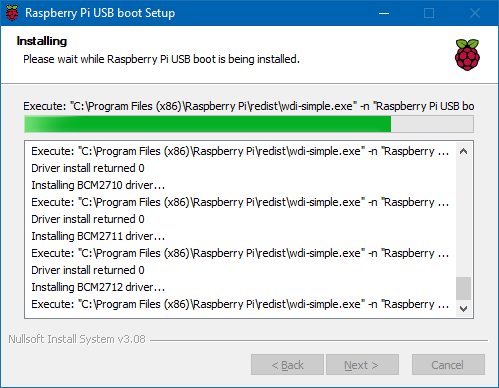
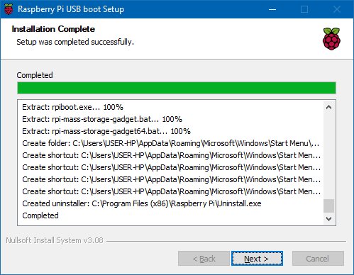
With the board powered off fit USB Boot/programming jumper link to Enable (to allow programming)
Connect the mini USB connector by the HDMI connector to the PC using a USB A to micro B data cable then power up the board
Depending on the Compute Module type Windows may produce additional dialogues as it detects the device
Once that sequence has finished Windows has now installed the required drivers and you can power off the unit for a moment whilst we get the PC side ready for the next step.
When the RPi-Boot starts up it’ll sit and wait for the attached board to boot up :
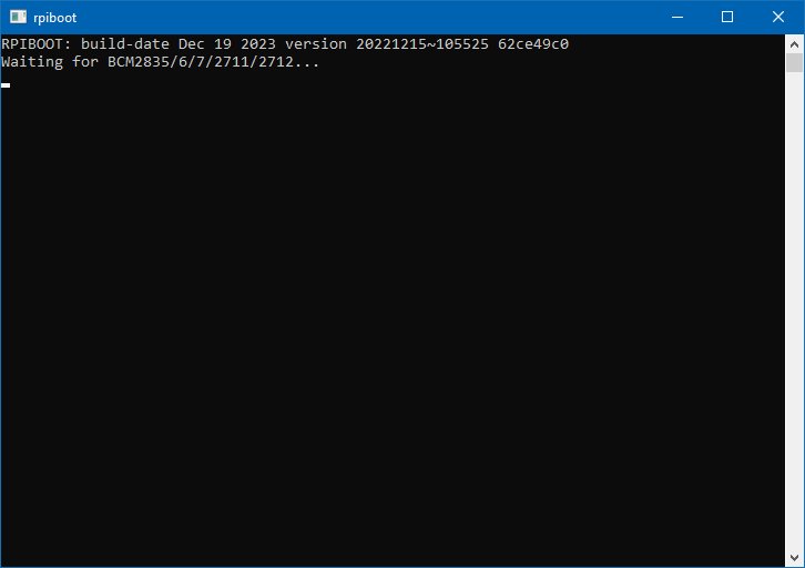
RPi-Boot essentially catches the board at power up and sends a series of commands to re-configure the compute module into mass-storage device mode, doing so allows Windows to recognise it as a new drive and we can then write the main OS image onto it.
So leave RPi-Boot running and waiting as shown above and power up the unit again.
If all goes well RPi-Boot will detect the attached board as it powers up, do it’s work and exit quickly, disappearing from the screen.
Here’s a grab of it in action :
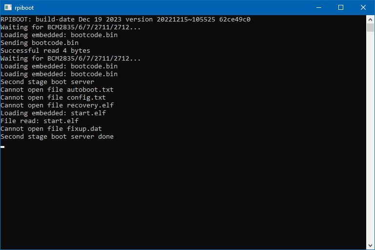
Note : Sometimes RPi-Boot doesn’t correctly catch the board as it boots and as a result the re-config sequence doesn’t complete correctly. In this case the simplest thing to do is to switch the board off, close then restart RPi-Boot and then power the board back on to try again.
When done the compute module will alternate into mass storage mode (so behaving just as though it's a USB memory stick) and Windows will then recognise the module as an external drive.
Windows will then assign drive letters to the detected partitions on the device, and then bug you about formatting them. If the module already contains an OS image it will show multiple drives as it assigns them to partitions, if the device is blank only one partition will be detected and a single letter assigned.
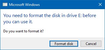
Click cancel to close this Windows Format dialog box(s) and we’ll load the OS next using another utility.
If the compute module has already been programmed Windows will recognise the FAT partition and assign that (at least) a drive letter, this is useful in the event that a config error with the boot files is made and needs recovery actions to be performed (e.g. dt-blob.bin or config.txt).
There are a few ways we can load on the OS, but for simplicity we’ll use one of the recommended OS writing software for writing the OS image.
The process below writes a disk image containing the partition table and both FAT boot partition and Linux ext partitions over the entire disk using a third party software tool :
- Download the Win32DiskImager utility from the Sourceforge Project page
- Install and then run the Win32DiskImager utility.
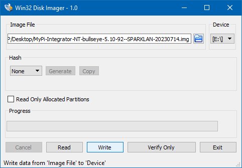
- Select the OS image file you wish to write
- Select the drive letter of the compute module in the device box (in our case E:) - if the module contains an OS image you will get multiple drive letters, e.g. E: & F: use the first one assigned (E:).
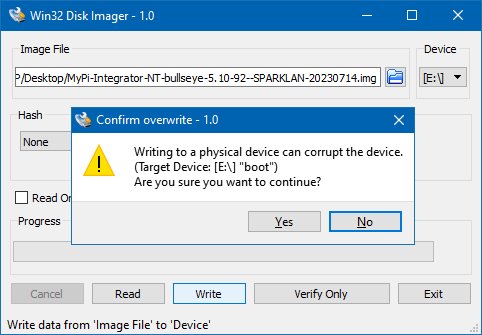
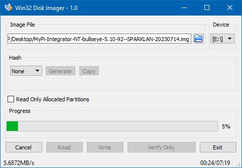
- Click Write and confirm that you wish to overwrite the disk wait for the write to complete.
Take care during this process not to dislodge any cabling as this will cause the program to error out and you’ll need to power off/on and start again from the RPI-Boot point.
Here's some grabs of this sequence :
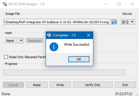
IMPORTANT : Once complete power off the unit and set the USB Boot jumper link back to Disabled, and remove the USB programming cable.
Failing to do both these steps will prevent the units onboard USB peripherals from working due to CM's USB master being still switched over to the programming socket and not the internal bus.
Power the board back on and it should now boot into the OS.
The same utility can also create snapshot images of the current image config to save time, although note this is a straight binary dump of the entire 8+GB disk not just the parts with files in so the image files end up quite big and take a long time to read/write.
Note that the official Raspbian images can be found here :
https://www.raspberrypi.com/software/operating-systems/
The Lite image version are the headless operating version without the GUI Interface installed.
Mass Programming PCBs
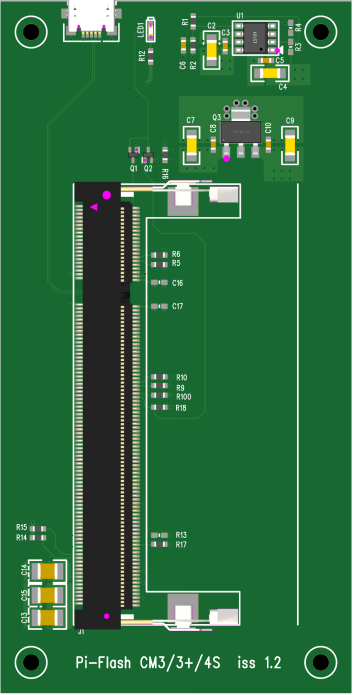
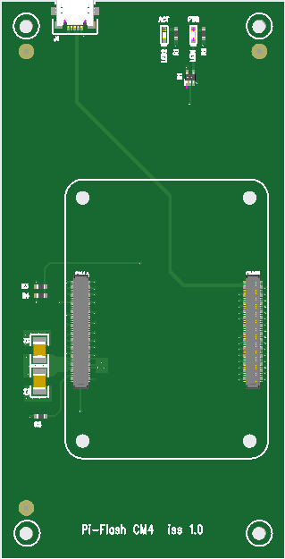
We have created some PCBs for fast flashing multiple Compute Modules using externally powered USB hubs, these data files are provided free of charge and include all the files needed to order from JLC PCB including the assembly and component data.
| Compute Module 3/3+/4S | Compute Module 4 |
|---|---|
 |
 |
| Download PCB Files | Download PCB FIles |
Mass Programming Software
With some care and additional hardware Balena Etcher can be configured to create a low cost mass programming station.
You will need the below parts
- - Version 1.14.3 of the Linux OS app (Windows version not recommended as it has issues with reliably detecting multiple CMs)
- - Set of Mass Programming PCBs (see above)
-
- Multiport Powered USB Hub
-
- USB to Micro USB cables
- - A cheap laptop that can be re-purposed to have Linux Installed (we recommend Debian 12)
Install Linux on the Laptop, install the etcher app from the balena-etcher_1.14.3_amd64.deb file
Note that Etcher will not detect the Compute Module unless it is run as root user
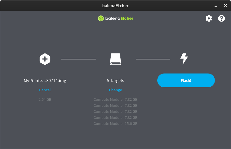
To configure the system to auto select all compute modules as targets, we need to make a change to the configuration file as shown below
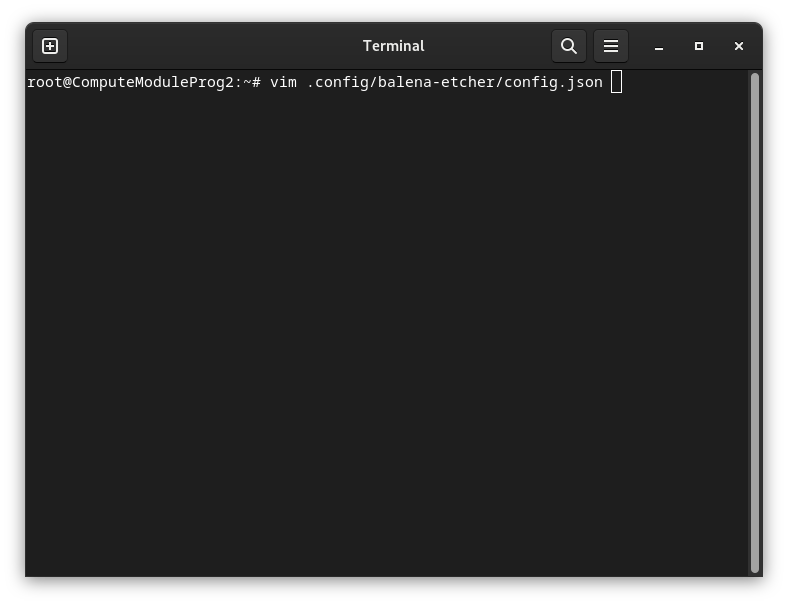
Add the config line at the bottom as shown
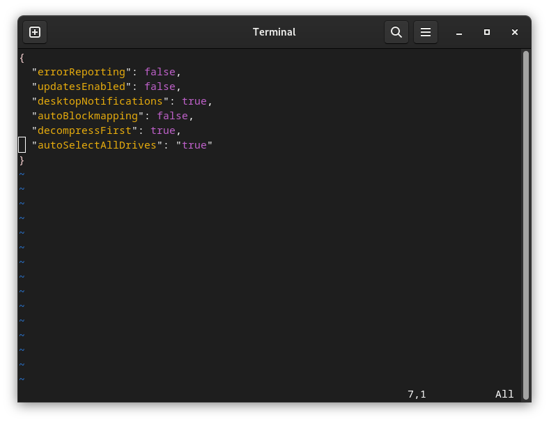
Image Downloads
The default images for the different products can be downloaded here :
Integrator Board NT (CM3+/CM4S)
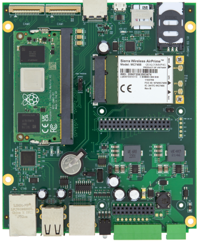
Bullseye OS 5.10.92 For Integrator Board NT (CM3+/CM4S) Iss 20230714
Integrator Board XT (CM4)
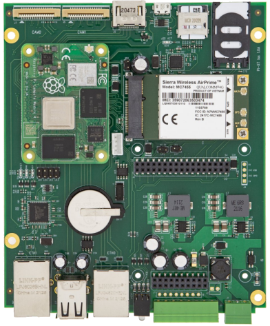
Bullseye OS 5.10.92 For Integrator Board XT (CM4) Iss 20240712.img
ntegrator Board SE (CM4)
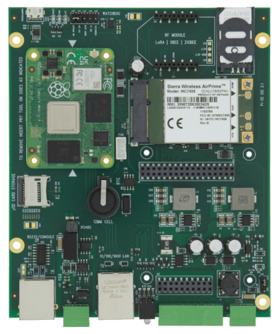
Bullseye OS 5.15.92 For Integrator Board XT (CM4) Iss 20250417.img
Edge Gateway
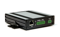
EdgeGateway-v1.44-Stretch_4.14.94-inc_SparkLAN_WiFi (CM3/CM3+) (v31/Jul/2019)
EdgeGateway-v1.5-Buster_4.19.118-inc_SparkLAN_WiFi (CM3/CM3+) (v14/Aug/2020)
EdgeGateway-v1.5-Buster_4.19.118-inc_SparkLAN_WiFi (CM3/CM3+) (v20/April/2022)
EdgeGateway-v1.5-Bullseye_5.10.92-inc_SparkLAN_WiFi (CM3/CM3+) (v11/April/2022)
EdgeGateway-v1.5-Bullseye_5.10.92-inc_SparkLAN_WiFi (CM4S) v20220324
Integrator Board (CM3/CM3+)
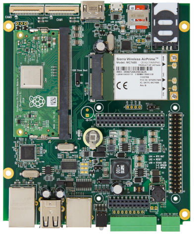
MyPi-Iss2.4-Stretch_4.14.94.img For CM3/CM3+ (v31/Jul/2019)
MyPi-Iss2.4-Buster_4.19.118.img For CM3/CM3+ (v20/April/2022)
MyPi-Iss2.4-Bullseye_5.10.92.img For CM3/CM3+ (v20/April/2022)
NOTE : The default MyPi root password is "root" please change this asap.