ISO-RF IO Card Configuration
The XBEE-RF card provides 4 x Digital Inputs (>=5V Input) as well as an XBEE style RF Module Socket
The following line needs to be added to /boot/config.txt to enable the hardware UART0 to appear on the correct pins for the adapter card :
dtoverlay=mypi-uart0,txd1_pin=32,rxd1_pin=33
This enables /dev/ttyAMA0 and the serial lines are connected to the ARF/XBEE Socket Pins 2 & 3
If you require the RTS/CTS lines use the uart0-full overlay and short solder Links LK1 & LK2 on the MyPi RF card to enable the RTS/CTS lines to the appropriate pins.
The board also connects the XBEE Reset line to GPIO6 incase you need to reset the module (or the module needs a reset to wake it up initially)
Here are two methods of communicating with your XBEE and getting it into command mode
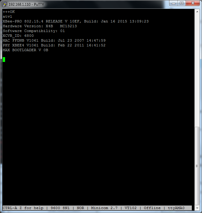
Minicom
This is slightly less awkward than with the LoRa module but still needs a few configuration changes before it will respond correctly
In this example we're using an XBEE module connected to the RF card (so the serial port is the ttyAMA0 port)
Start minicom
# minicom -D /dev/ttyAMA0 -b9600
Then re-configure the serial port to have no hardware handshaking, enable local echo and linefeed (CTRL-a e CTRL-a a CTRL-a o)
When using minicom the initial +++ should not have a carriage return after it, just type these three plus signs leaving a 1 second gap before and after it without any keys pressed and wait for the OK response.
Note that the +++ cannot be entered using the numeric keypad
You can then type the AT commands and press enter each time, but be quick as the command mode will time out after a short period of inactivity

Python
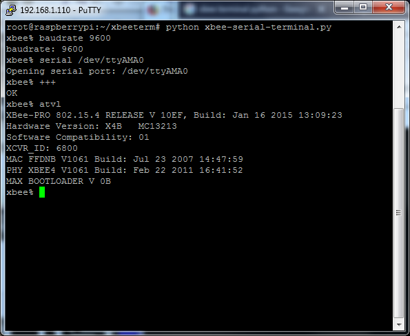
Alternatively we can use a python terminal program like this one : https://github.com/sensestage/xbee-tools
Here do the below :
# apt-get install python-serial
# mkdir xbeeterm
# cd xbeeterm
# wget https://raw.githubusercontent.com/sensestage/xbee-tools/master/python/xbee-serial-terminal.py
# wget https://raw.githubusercontent.com/sensestage/xbee-tools/master/python/xbee.py
# python xbee-serial-terminal.py
On the XBEE module we tested you needed to set the baud rate to 9600
In this case you need to press return after each command (including the +++ at the start)

The RF card has 4 Dig Input lines for general usage, the GPIO lines are connected to is as follows :
GPIO38 => DIGIN1
GPIO41 => DIGIN2
GPIO42 => DIGIN3
GPIO43 => DIGIN4
The easiest way to configure this is via the command sequence below as root user :
# gpio export 38 in
# gpio export 41 in
# gpio export 42 in
# gpio export 43 in
# ln -s /sys/class/gpio/gpio38/value /dev/diginput0
# ln -s /sys/class/gpio/gpio41/value /dev/diginput1
# ln -s /sys/class/gpio/gpio42/value /dev/diginput2
# ln -s /sys/class/gpio/gpio43/value /dev/diginput3
This will create the below shortcuts :
# ls -l /dev/dig*
lrwxrwxrwx 1 root root 28 Mar 10 12:00 /dev/diginput0 -> /sys/class/gpio/gpio38/value
lrwxrwxrwx 1 root root 28 Mar 10 12:00 /dev/diginput1 -> /sys/class/gpio/gpio41/value
lrwxrwxrwx 1 root root 28 Mar 10 12:00 /dev/diginput2 -> /sys/class/gpio/gpio42/value
lrwxrwxrwx 1 root root 28 Mar 10 12:00 /dev/diginput3 -> /sys/class/gpio/gpio43/value
To read a digital input state :
$ cat /dev/diginput0
0
$ cat /dev/diginput0
1
One of the neat features of DIGI XBee Modules is the ability to go into transparent serial mode, for information see here
Digi XBEE Transparent Serial Comms
For more information on the usage of the RF modules please consult the suppliers website directly